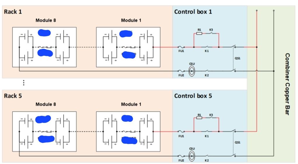
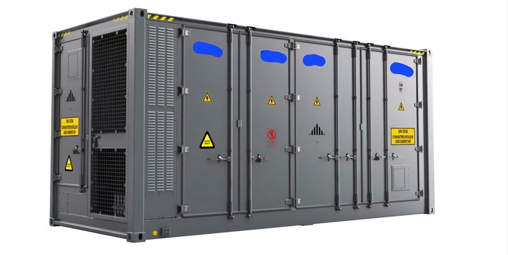
The Battery system is composed of 5 battery racks in parallel.
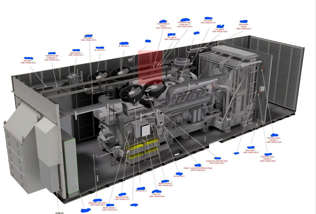
Liquid cooled energy storage container overview-inside
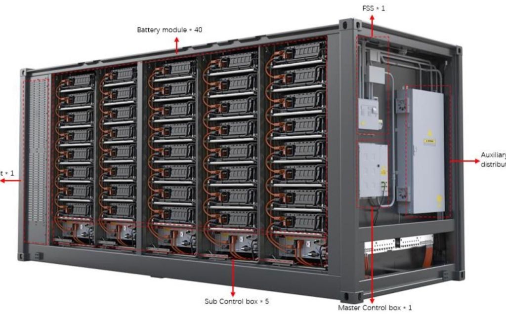
The Battery system composed of 5 battery racks in parallel. Each battery rack contains 8 battery modules, each battery module is composed of 104pcs battery cells in series connection, so the battery system contains 4160 battery cells.
Battery container is the core unit in the energy storage system and acts as the equipment for storing electrical energy. It can be applied to many applications including renewable energy integration, frequency regulation and voltage regulation of the grid.
Battery containers consists of battery system, battery management system (BMS), fire suppression system (FSS), thermal management system (TMS) and auxiliary distribution system.
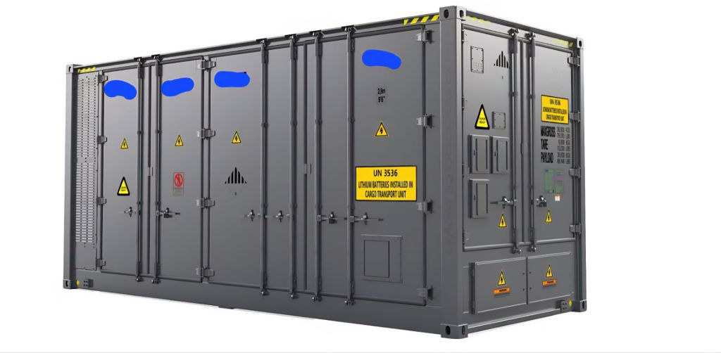
Battey container- Right side overview Battery container- Left side overview
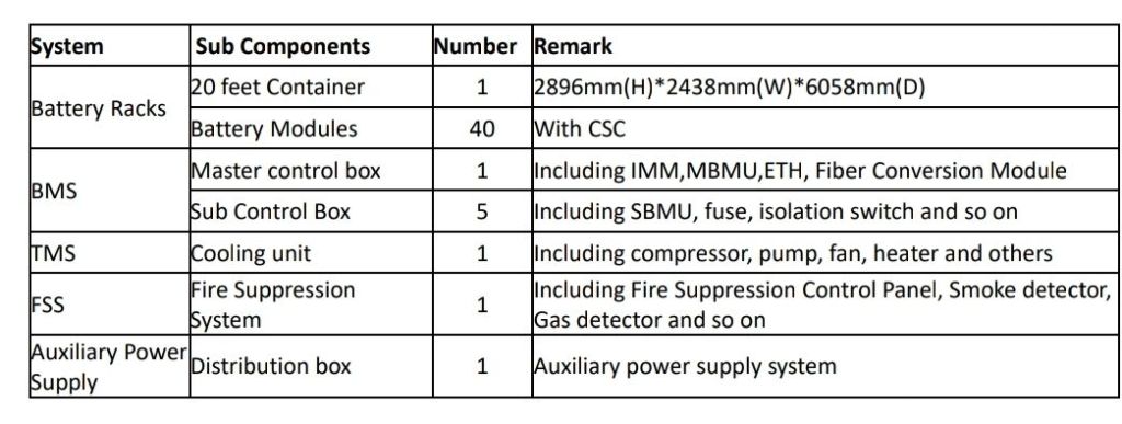
The basic units of the whole system is listed as following:
In the next post, we will go more into detail of the battery rack system overview.
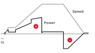
According to the “Maximum Power Method” in NFPA 70E, the estimated DC arc flash incident energy at the maximum power point can be calculated, and then the hazard boundary is defined as the following figure.
Arc Flash Label
2. Personal Protective Equipment (PPE)
The PPE is determined by the incident energy which is the temperature produced (in cal/cm2) at a distance (usually eighteen inches) from an arc flash.
PPE requirements for EnerC+ battery container operational precautions is category 3.
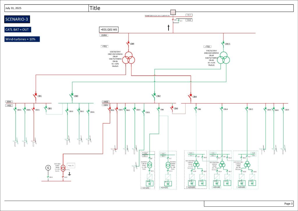
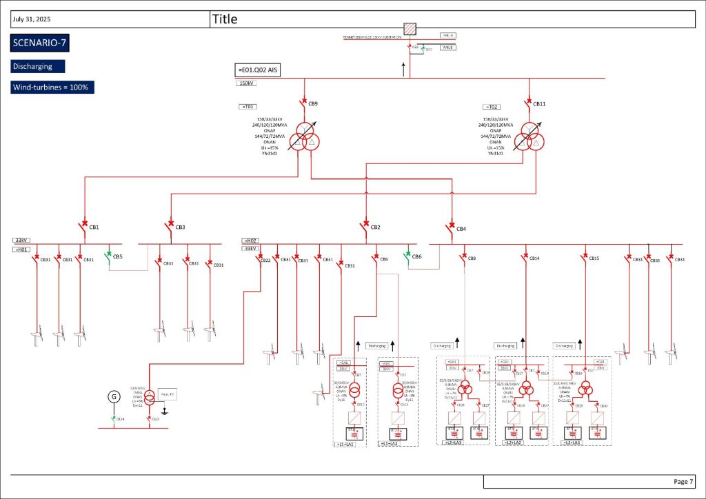
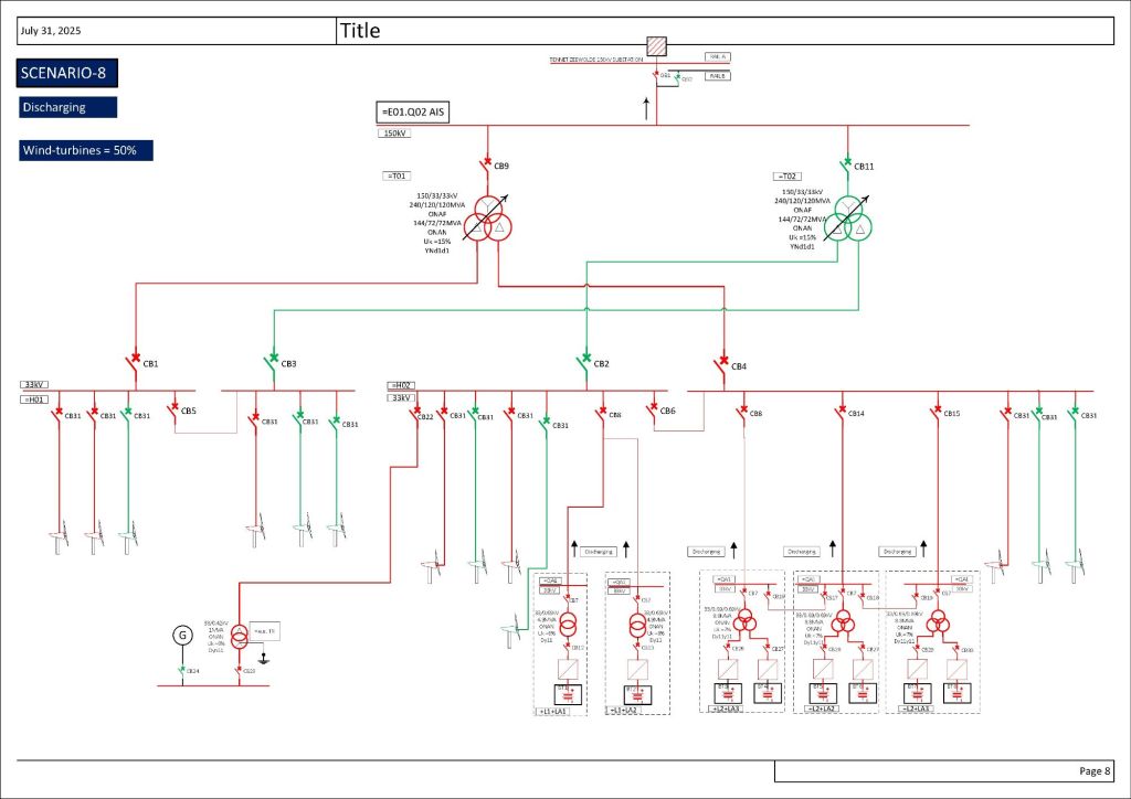
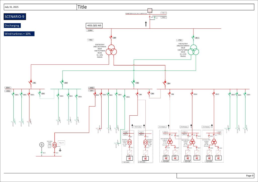
Please look at 9 different scenarios I have listed in the following pictures and share your ideas.
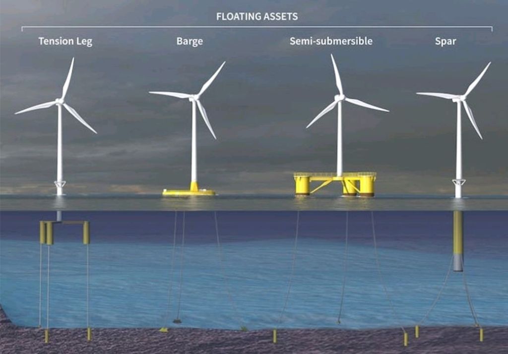
BESS plant has been connected to an upstream 150kV national grid that is already energized by wind turbines (Wind Park). Batteries could be charged by upstream grid or discharged to upstream grid.
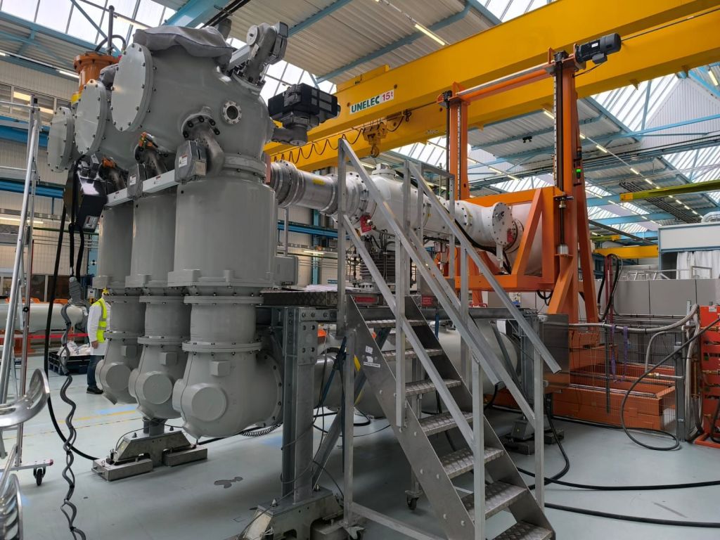
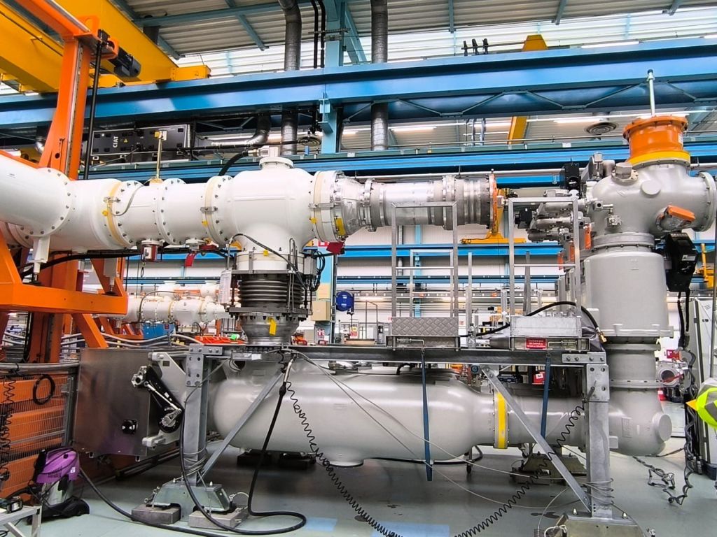
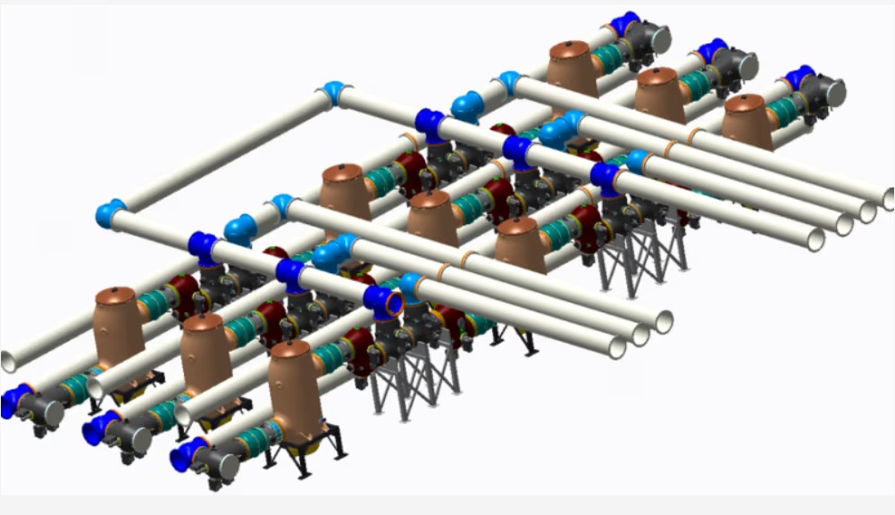
In large countries such as India, China or Brazil, conventional and new sustainable power sources are often located in regions remote from load centres and need large-scale AC transmission systems. One solution to reduce the power losses and improve the transmission capacity of AC links is to increase the system voltage up to 800–1,200 kV AC. For these high-voltage transmission systems, the use of gas-insulated substations (GIS) is extremely advantageous, as this substation type is highly reliable and requires less maintenance than air-insulated substations (AIS) because all active parts are protected from environmental hazards. In addition, a GIS’s inherent compactness (owing to the superior insulating properties of SF6 compared with air) reduces bay dimensions and overall substation footprint and height, which is very important in minimising seismic impact.
Responding to a growing demand for greater compactness (notably from the Indian utilities), the main objective was therefore to develop an 800 kV GIS compact enough to be installed in a small building. One key point is the circuit breaker architecture, as it represents a large part of the substation.
Innovative circuit breaker architecture with smaller footprint and reduced height
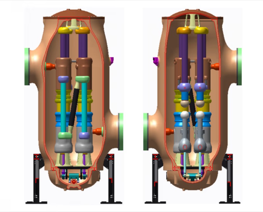
The solution was found by positioning the two chambers vertically, side by side, in a single tank, with an oblique conductor in between. This enables us to have the two breakers as close as possible to each other – the shortest distance between them is less than 5 cm. The chambers can also be equipped, where necessary, with closing resistors without greatly increasing the dimensions of the enclosure.
Circuit breaker section view
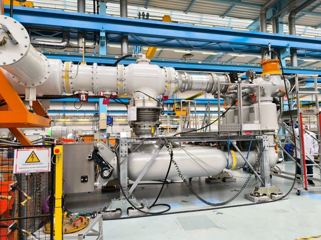
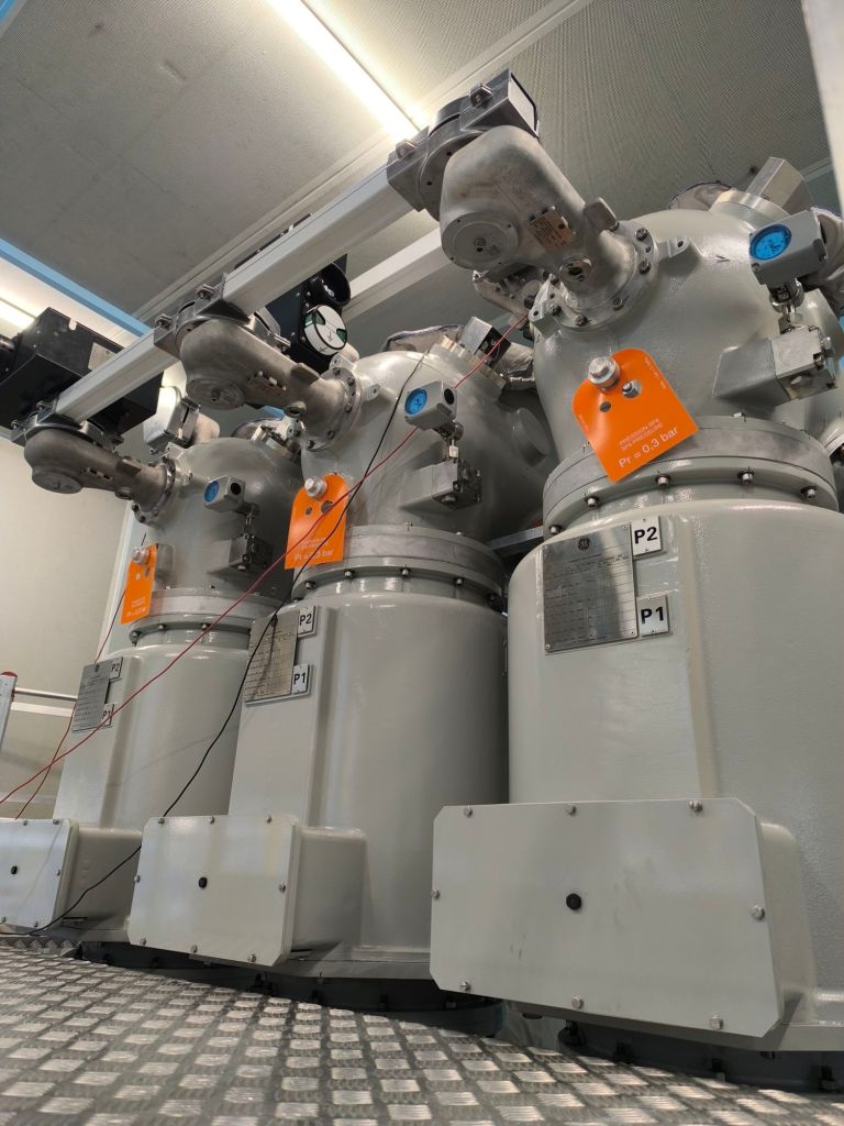
With this innovative circuit breaker design, improved substation architecture and other innovations (see below), new 800 kV GIS not only achieves the reduced footprint required but also, with a maximum height of 5 meters as for the standard architecture, can be easily installed inside a building. Moreover, even though it is the most compact 800 kV GIS, the unit still offers exceptional access to all components and viewports: the highest drive position is at 3 meters, readily viewable from the floor without requiring specific – and heavy – catwalks.
Typical diameter arrangement inside a building
Another important objective was to ensure reliability under any and all service conditions, particularly with respect to earthquakes. “As India – a major developing network using 800 kV GIS – can be subject to serious seismic events, taking this risk into consideration in the very early stages of the design of our new substation. Having a reduced height is already a good point where a high level of seismic withstand is required.
In addition, all the most massive equipment is close to the floor (hence a low centre of gravity), and seismic calculations have been conducted jointly with design studies to ensure optimum behaviour of the substation.
As a result, 800 kV GIS offers top-class safety with regard to seismic constraints of 0.3 G and more.
Performance and reliability
Development of equipment for such high-voltage ratings cannot be made by simply applying a size-factor ratio from lower voltage products. The characteristics of UHV overhead lines and substation schemes demanded the continuation of fundamental studies and the application of innovative solutions to achieve maximum reliability for the equipment.
For instance, when the service voltage rises, the bus charging current switching(BCCS) capability of a disconnector has to be increased. As a consequence, managing BCCS implies a better understanding of the complete phenomenon. When the circuit breaker opens, the load current is interrupted and only a small capacitive current can flow through the closed disconnector. During the opening operation, multiple restrikes can be observed between contacts.
The main issue in disconnector development is to ensure that no flashover between the two electrodes will propagate and reach the enclosure.
An innovative solution has been found, applied and validated: a specific characteristic of the electrode, which includes mobile parts, allows the gap to be reduced during the closing operation. The reliability of the disconnector in terms of very fast transient overvoltage (VFTO) phenomenon is therefore increased. At the same time, bus transfer performance has also been studied in depth, for all voltage levels, in order to be able to comply with IEC standard requirements (and even beyond, as some customers may demand). To do so, an innovative concept of mobile arcing contact was developed , combining fast translation and rotating displacement. This new solution, which is patented, has been tested and validated on a prototype 800 kV GIS rolled out for the production systems.
Disconnector section view
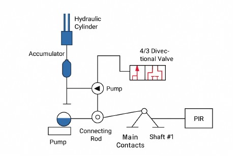
The kinematics of the equipment was also a topic of concern. A multi-domain simulation program (like Amesim) was used to model many possible kinematics combinations and to enhance connecting rods, crank handles and hydraulic drive to have minimum energy consumption for the required opening and closing speeds. The kinematics of the circuit breaker is driven by a single hydraulic command, even in the case of a circuit breaker connected with pre-insertion resistor (PIR). The actuation system is installed at the bottom of the circuit breaker tank and moves two different shafts, one for the chambers and one for the PIR.
Hydrolic and Mechanical Amesim Diagram
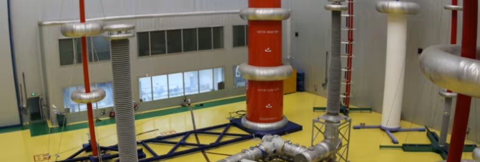
Fully IEC compliant, even for the most constraining performance
Particular efforts have been made to ensure that the 800 kV GIS meets foreseeable reliability requirements. It has been successfully subjected to all IEC-type tests: dielectric testing and temperature rise, bus charging current switching and bus transfer for the disconnector, making test for high speed earthing switch, terminal faults, short line faults and capacitive switching for the circuit breaker. The result of this complex development project, which required enhanced international collaborative R&D work, is a cutting-edge 800 kV GIS that is super compact, highly reliable and easily maintainable.
The compact and robust liquid-cooled cabinet drives are an utlimate solution for various applications where space savings, silent operation or durability in harsh environments is a must.
Through built-in redandancy of parallel connected modules, enables higher drive availability and greater process uptime. If one of the moduels is not operating or is being maintained , the drive will continue to operate at partial load.
Advanced liquid cooling and optimal design
Direct liquid cooling offers easy heat transfer without air filtering problems. As the coolant takes care of 98% of the heat losses , no additional filtered air cooling is needed. This increase the total efficiency of the drive installation.
For harsh enviromental conditions
The totally enclosed cabinet structure makes the liquid-cooled drives perfect for harsh environmental conditions, like marine and offshore requirements, and the drives have marine type approvals from various classification bodies.
As the direct liquid cooling enables silent operation , makes them suitable for applications where noise levels are an important environmental factor.
Robust , reliable and compact
Highly efficient liquid cooling removes the need for air conditioning in installation rooms, bringing installation and operating costs down. As there is no need for additional air-conditioning devices or air ducts, the installation is significantly simplified.
The used coolant type is Antifrogen® L. A cooling liquid with glycol and inhibitor. It is a ready-made, commercially available mix, which enables easy commissioning and maximized process uptime.
Highlights:
Advanced liquid cooling which reduces the need for air cooling in installation rooms.
High power density with compact design.
Redundancy possibility through parallel connected modules prevents unwanted process interruptions.
Low harmonic and regenerative variants.
Silent operation
Suitable for harsh environments
Marine approvals from various key classification bodies.
Regenerative drives are a solution for regenerative operation in cyclic or continuous braking applications. such applications include cranes, elevators ,centrifuges, downhill conveyers and test benches.
With regenerative functionality , the braking energy of the motor is returned to the drive and distributed to the supply network so that it can be utilized by other equipment. compared to mechanical or resistor braking, where braking energy is wasted as heat , regenerative drive operation offers significant energy consumption and cooling savings.
Possibility to regenerate 100% of power continuously
benefits:
Minimized downtime
The VFD will not interrupt the process or affect its quality in unstable supply network conditions. The drive’s active supply unit can boost the output voltage to enable full motor voltage, even when the supply voltage is below nominal value. This ensures reliable operation in weak networks. This voltage boost capability can also be utilized to overcome voltage drops caused by long supply or motor cables.
Optimized cost and space
Everything needed for regenerative operation, such as an active supply unit and a low harmonic line filter are integrated into the drive, and no external braking devices are needed.
Advantages:
Quick, easy drive installation
Small installation footprint
No need to add cooling to handle the heat generated by mechanical or resistor braking
simplified wiring
Fewer spare parts needed
The drive’s voltage boost capability can be an advantage in motor dimensioning. With a higher motor voltage, the same power is achieved with less current, which improves motor efficiency and may allow a smaller motor to be used.
The drives also can offer a possibility of network power factor correction to compensate for the low power factors of equipment connected to the same network. It reduces the need for additional power factor correction equipment such as filters and large capacitor banks.
Maximize motor performance and efficiency
The drive can provide full motor voltage, even if the supply voltage fluctuates. Regeneration can occur for as long as necessary and as often as needed.
The drive features direct torque control (DTC) provides precise speed and torque control for maximum motor performance and motor efficiency.