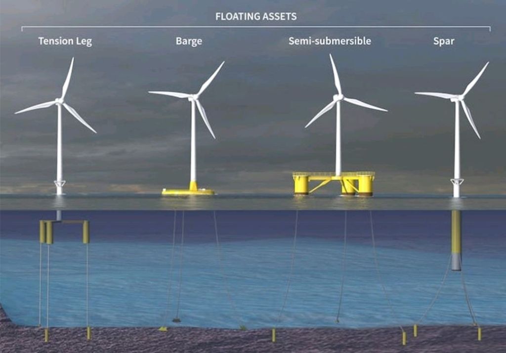
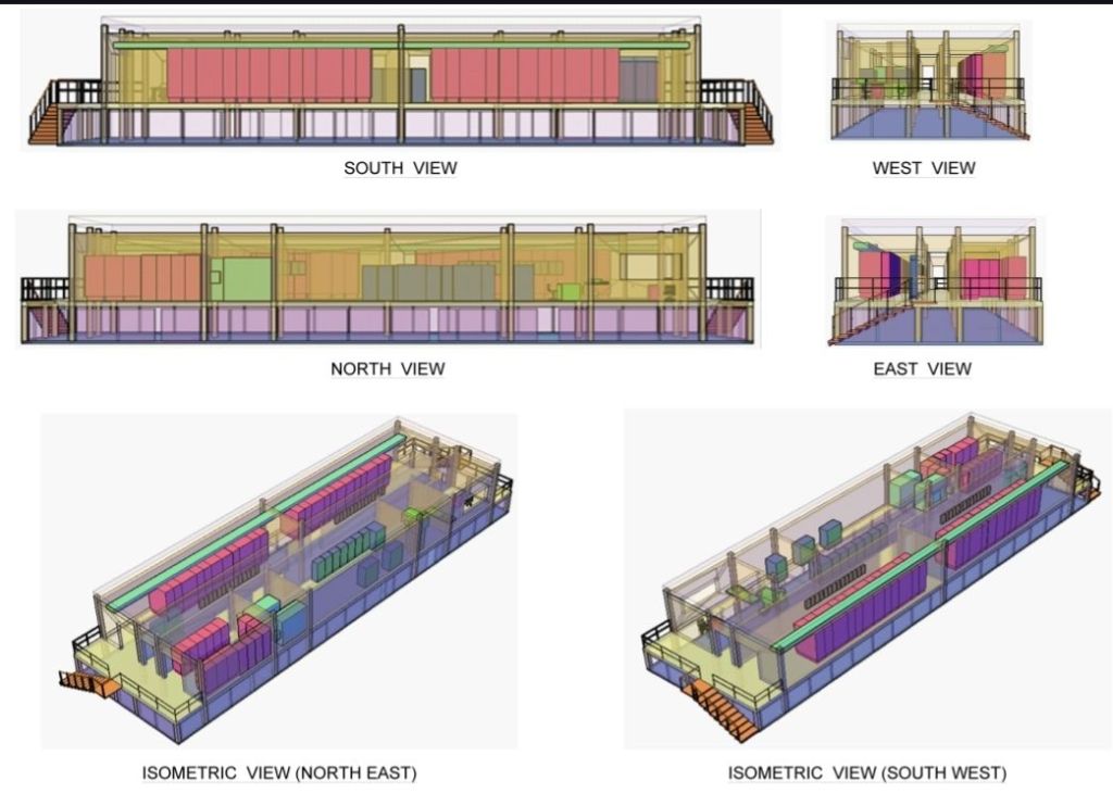
- Tension Leg
- Barge
- Semi-submersible
- Spar
AC LOAD FLOW
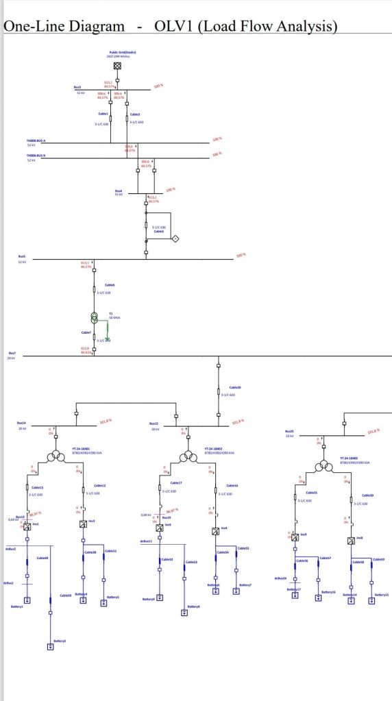
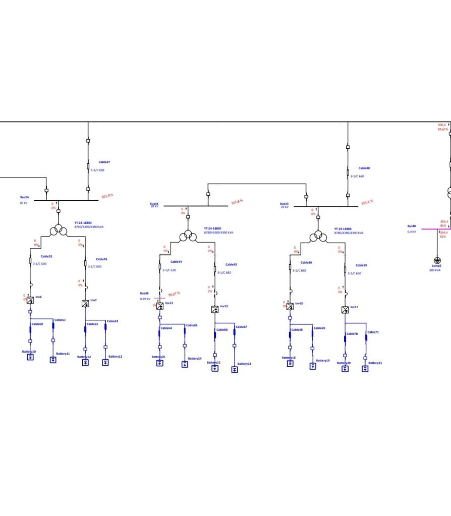
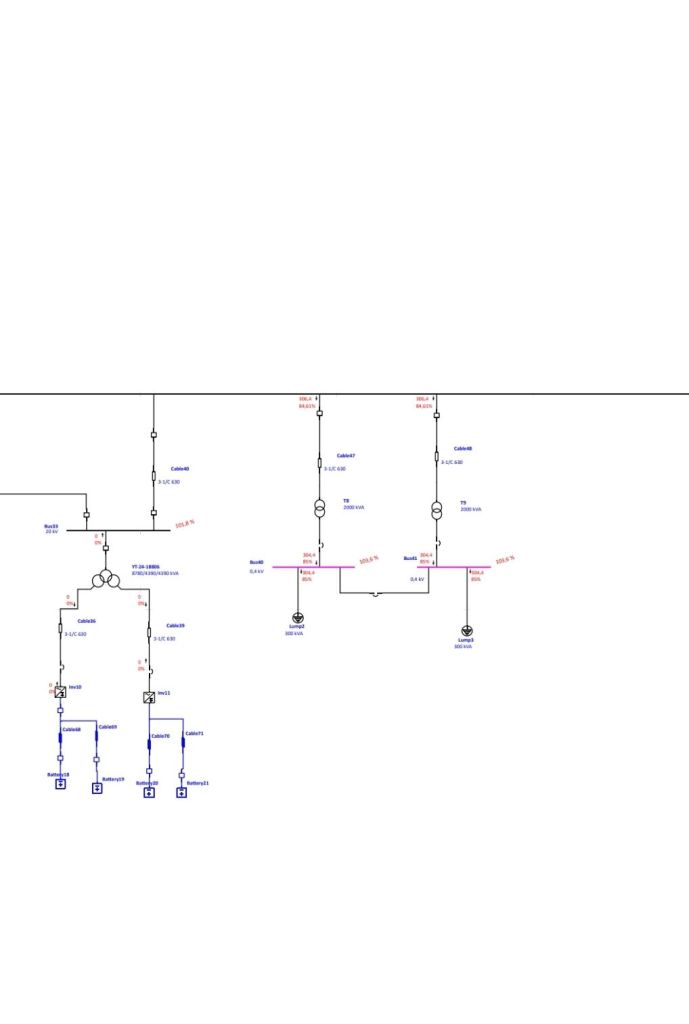
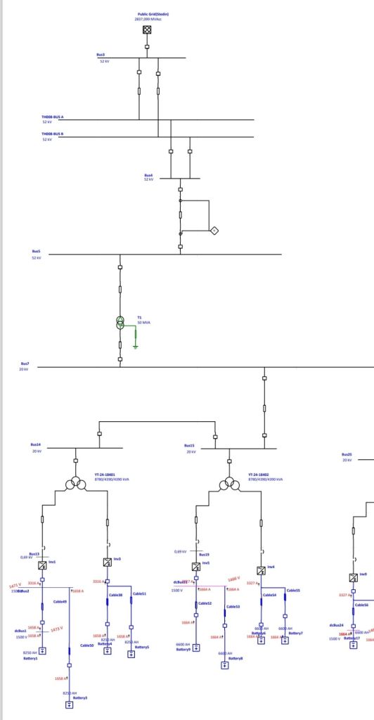
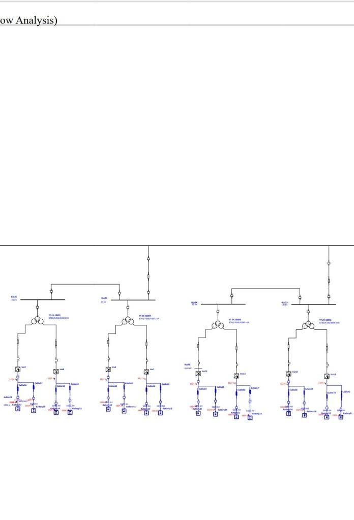
DC LOAD FLOW

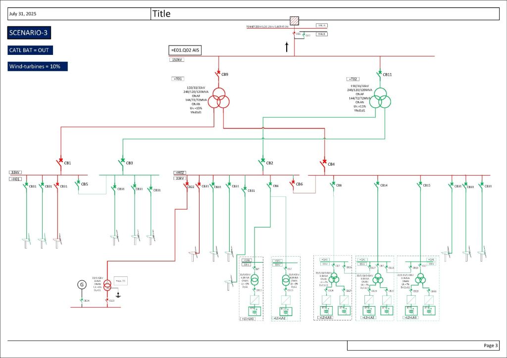
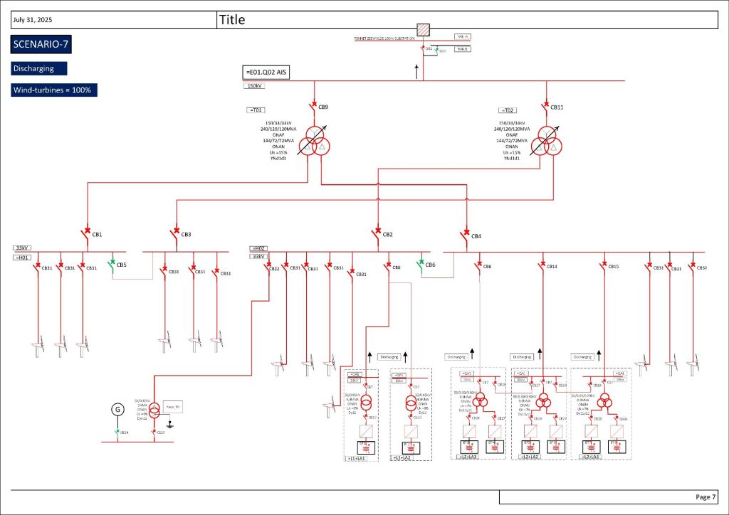
Please look at 9 different scenarios I have listed in the following pictures and share your ideas.
BESS plant has been connected to an upstream 150kV national grid that is already energized by wind turbines (Wind Park). Batteries could be charged by upstream grid or discharged to upstream grid.


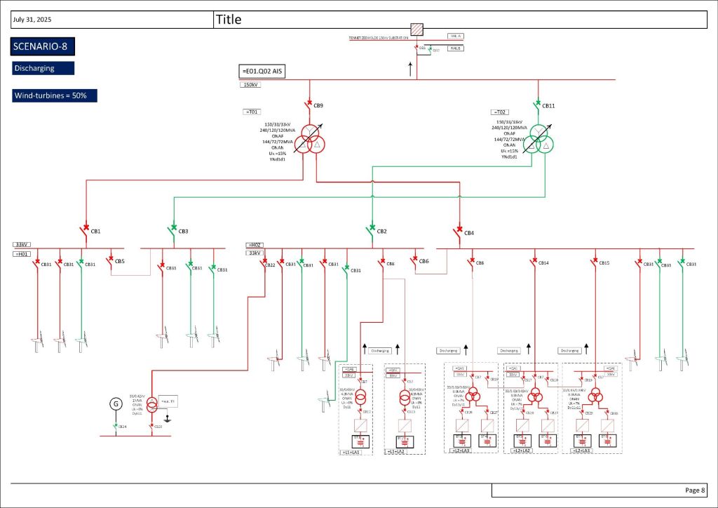
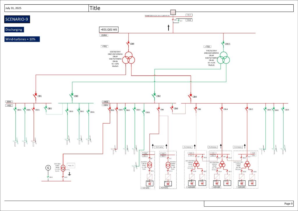
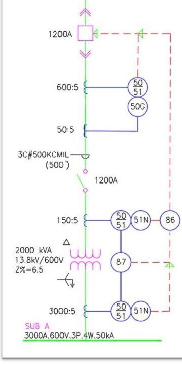
single Line Diagram of an electrical installation represents the main electrical equipment in the system, including: